- Free Consulting : (+91) 9822555277
- [email protected] | [email protected]

SHUT OFF VALVES
Technical Data
Introduction
Refrigerants
Shut off valves are applicable to all common non-flammable refrigerants including R717 and non-corrosive gases/liquids dependent on sealing material compability. For further information please see installation instruction for CSVA. These Shut off Valves are used in the Industrial Refrigeration system.
Temperature range
Standard version : - 46/+150°C
Pressure range
shut off valves are designed for max, working pressure CSVA-2 DN-15 to DN-40 : 25 bar (362 psig) CSVA-4 DN 15 to DN 200:40 bar (580 psig)
Design
Housing
Made of special, cold resistant steel.
Connections
Available with the following connections: - Butt-weld ANSI DN15-40(B 36.10 Schedule 80) Butt-weld ANSI DN 50(B 36.10 Schedule 40) Butt-weld ANSI Socket weld (ANSI B 16.11) - DN 15 - 40 % -1% in.).
Valve Cone
Spindle
Made of polished stainless steel so that PTFE and Graphite gaskets are not damaged.
Sealing
Spindle sealing is done with PTFE and Graphite gaskets assuring 100% sealing.
Features
Housing
Made of special, cold resistant steel.
Valve cone
Shut off valves cone can be turned on the spindle, thus there will be no friction between the cone and the seat, when the valve is opened and closed.
Spindle
Made of polished stainless steel so that PTFE and Graphite gaskets are not damaged.
Sealing
Spindle sealing is done with PTFE and Graphite gaskets assuring 100% sealing.
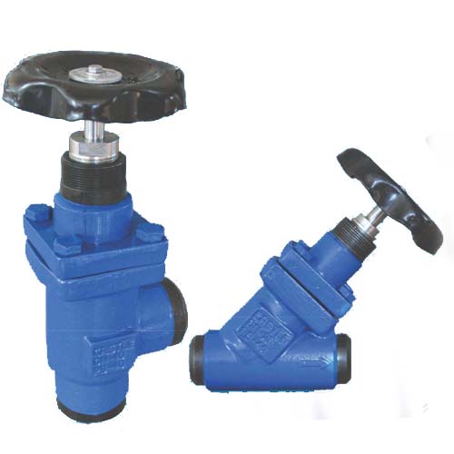
HAND REGULATING VALVES
Introduction
CREG is angle-way and straight-way regulating valves, which act as normal stop valves in the closed position. Regulating valves are designed to meet the strict quality requirements on refrigerating installations and are carefully designed to present favorable flow conditions and accurate linear characteristics CREG is equipped with internal back seating enabling the spindle seal to be replaced with the valve still under pressure.
Technical data
Refrigerants
Applicable to all common non flammable refrigerants including R 717 and non corrosive gases/liquids dependent on sealing material compability.
Flammable hydrocarbons are not recommended. For further information please contact your local Castle Sales Distributor.
Temperature range
CREG: 46/+150°C.
For further information please see installation instruction for CREG
Pressure range
Max. operating pressure:
CREG: 25 bar g (362 psig)..
Features
- Applicable to all common non flammable refrigerants including R 717 and non corrosive gases/liquids dependent to sealing material compatibility.
- Designed to ensure perfect regulation.
- Internal backseating enables replacement of the spindle seal whilst the valve is active, i.e. under pressure.
- Easy to disassemble for inspection and possible repair.
- Max. operating pressure: CREG: 25 bar g (362 psig) Full temperature range packing gland - 46/+150°C.
Housing
Made of special, cold resistant steel.
Valve cone
The valve cone can be turned on the spindle, thus there will be no friction between the cone and the seat, when the valve is opened and closed.
Spindle
Made of polished stainless steel so that PTFE and Graphite gaskets are not damaged.
Sealing
Spindle sealing is done with PTFE and Graphite gaskets assuring 100% sealing.
Design
Housing
Made of special, cold resistant steel.
Connections
Available with the following connections: - Butt-weld ANSI DN15-40(B 36.10 Schedule 80) Butt-weld ANSI DN 50(B 36.10 Schedule 40) Butt-weld ANSI Socket weld (ANSI B 16.11) - DN 15 - 40 % -1% in.).
Valve cone
The valve cone is designed to ensure perfect regulation. A cone seal ring provides perfect sealing at a minimum closing momentum. The valve cone can be turned on the spindle, thus there will be no friction between the cone and the seat when the valve is opened and closed.
Packing gland-CREG
The "full temperature range" packing gland ensures perfect tightness in the whole range: -46/+150°C.
Installation
Install the valve with the spindle up or in horizontal position. The flow must be directed towards the cone. The valve is designed to withstand high internal pressure. However, the piping system in general should be designed to avoid liquid traps and reduce the risk of hydraulic pressure caused by thermal expansion.
For further information refer to installation instruction for CREG
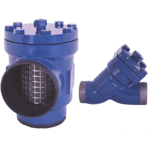
STRAINER
Introduction
CFIA filters are a range of angle-way and straight-way filters which are carefully designed to give favorable flow conditions. The design makes the filter easy to install and ensures quick filter inspection and cleaning, CFIA filters are used ahead of automatic controls, pumps, compressors, etc. for initial plant start-up and where permanent filtration of the refrigerant is required. The filter reduces the risk of undesirable system breakdowns and reduces wear and tear on plant components CFIA filters are equipped with a screen mesh of stainless steel, available in sizes 100, 150, 250 and 500p (microns), (US 150, 100,72,38 mesh").
Technical data
Refrigerants Applicable to all common refrigerants including flammable refrigerants and all non-corrosive gases/liquids For further information please see installation instruction for CFIA.
Temperature range
Temperature range - 46"C/4150°C.
Pressure range
Max. working pressure: CFIA: 40 barg (580 psig).
Features
- Applicable to all common refrigerants and all noncorrosiv gases/liquids
- Filter net of stainless steel mounted direct without extra gaskets means easy servicing
- CFIA filter housing compatible with housings belonging to other Castle products. A compatibility overview can be obtained from local Castle Sales Distributor
- Mesh is the number of threads per inch. (microns) is the distance between two threads (1=1/1000 mm).
- CFIA 50-200 (2-8 in) can be equipped with a magnetic insert for detention of iron particles and other magnetic particles.
- Each filter clearly marked with type, size and performance range.
- Housing and bonnet of low temperature steel.
- Temperature range-46°C +150°C.
- Pressure range: CFIA: 40 barg (580 psig).
Design Connections
Available with the following connections:
- Butt-weld ANSI (836.10 Schedule 80), DN 15-40 (1/2-11/2 in.)
- Butt-weld ANSI (B36.10 Schedule 40). DN 50-200 (2-8 in.)
Filter Insert
A filter grid and filter net of stainless steel ensure long element life. The filter net offers a very high degree of cleanability .
Housing
Made of special, cold resistant steel.
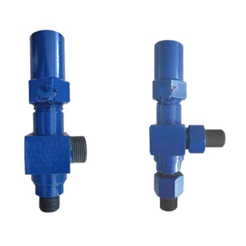
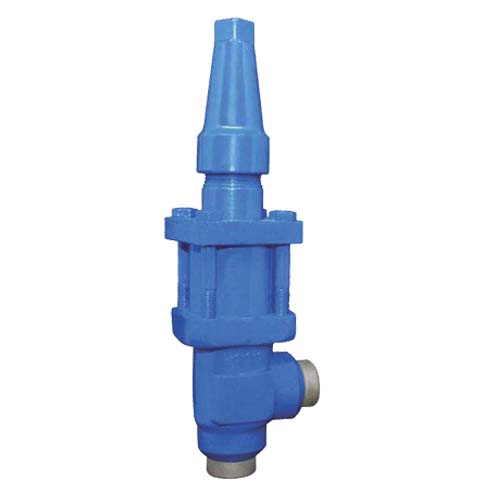
SAFETY RELIEF VALVES / DOUBLE STOP VALVES
CSRVA 15-25 are standard, back pressure dependent safety relief valves in angle-way execution, specially designed for the protection of vessels and other components against excessive pressure. The valve is designed to meet the strict quality demands and safety requirements for refrigeration installations, specified by the international classification societies. The valve is recommended as an external and internal safety relief valve in refrigeration plants. The spring housing is closed tightly to avoid refrigerant leakage.
The inlet flow diameters of the valves are:
- 13 mm (in.) for CSRVA 15
- Also utilized in chemical and petrochemical applications.
- 18 mm (3/4 in.) for CSRVA 20
- 23 mm (1 in.) for CSRVA 25
The valves can be delivered with set pressures between 10 and 25 barg (145 and 363 psig). valves can also be supplied with non-standard set pressures between 10 to 25 bar g (145 to 363 psig) to suit the customer's specific requirement.
Technical data
Technical data Applicable for the refrigerants R717 (ammonia, Nh3), HFC, HCFC (e.g. R22, R134a, R404a) and other refrigerants dependent on sealing materials compatibility within a temperature range of -30°C/+100°C Flammable hydrocarbons are not recommended.
Pressure
Pressure setting range: 10-25 bar (145-363 psig) the valve is designed for strength test : 40 bar (580psig). Leakage safety: Same as set pressure. For further information please contact your local Castle Sales Distributor.
Important:
The CSRVA safety relief valve is dependent on the back pressure (if the back pressure is higher than the atmospheric pressure, the opening pressure will be higher than stated set pressure) Special circumstances such as vibrations (which should be avoided) and oscillating pressure may require an increased difference between the operational pressure and the closing pressure.
Pressure Setting:
The operating pressure of the plant should be at least 15% below the set pressure. This allows a perfect re-seating of the safety relief valve after having been activated.
Temperature Range:
-30/+100°C.
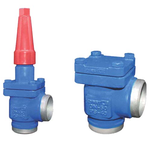
OVERFLOW VALVES
Technical Data
Introduction
Refrigerants
Applicable to HCFC, HFC, R717(Ammonia) and R744 (CO2). For further information please see installation information for COFV.
Temperature range
Standard version : - 46/+150°C
Pressure range
The valves are designed for max, working pressure 40 bar g(580 psig)
Features
Three functions in one valve. The OFV valve combines the functions of an overflow valve, a check valve and a stop valve COFV are angle-way overflow valves, which have adjustable opening pressure and cover the differential pressure range 2-8 bar (29-116 psi). The valve can be closed manually, during plant service and have back seating, enabling the spindle seal to be replaced with the valve still under pressure. The valves are specially designed to prevent fluttering due to low velocity In consequence it is possible to apply the valves with wide fluctuations in capacity demands and maximum performance to part load. A flexible O-ring provides perfect sealing over the seat.
Installation
The valve is designed to resist very high internal pressure, but as to the pipe system in general, hydraulic pressure caused by thermal expansions in entrapped refrigerants should be avoided.
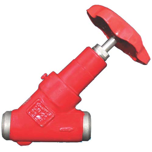
STOP CHECK VALVES
Technical Data
Introduction
Refrigerants
Applicable to all common non flammable refrigerants including R717 and non corrosive gases/liquids dependent on sealing material compatibility.
Temperature range
Standard version : - 46/+150°C
Pressure range
Range The valve are designed for max. working pressure 40 bar g (580 psig).
Features
The valve Designed to open at a very low differential pressure of 0.04 bar (0.58 psig) Designed with a built-in damping chamber preventing valve flutter, due to low refrigerant velocity and low density Easy to disassemble for inspection and service Internal back seating enables replacement of the spindle seal whilst the valve is active in under pressure Optimal flow characteristics ensuring quick opening to the fully open position.
Housing
Made of special, cold resistant steel.
Valve cone
The valve cone can be turned on the spindle, thus there will be no friction between the cone and the seat, when the valve is opened and closed.
Spindle
Made of polished stainless steel so that PTFE and Graphite gaskets are not damaged.
Sealing
Spindle sealing is done with PTFE and Graphite gaskets assuring 100% sealing.
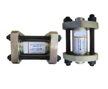
CHECK VALVES FOR AMMONIA & FLUORINATED REFRIGERANTS
Introduction
Check valve type CNRVA can be used in liquid,suction, and hot gas lines in refrigeration and air conditioning plant with ammonia. CNRVA can also be used in refrigerating systems with fluorinated refrigerants. When the CNRVA is used in liquid lines where cold thick oil or impurities may be present, it is recommended that the standard spring be replaced by a special spring.